
Wireless networks, cellular antennas, two-way radios, and communication equipment all produce radio frequency (RF) fields. Those fields are not equally strong everywhere. A reading may change between floors, beside a transmitter, or when nearby equipment switches on. Understanding what is present requires measurements taken under defined conditions.
An RF survey meter measures RF field levels within the frequency range supported by its probe and instrument. It is commonly used to compare locations, identify areas needing closer investigation, and collect data for exposure assessments.
But a number on a screen is not a complete assessment. The result must be interpreted in light of the instrument’s frequency coverage, measurement settings, nearby sources, site conditions, and the criteria being applied. This article explains what RF meters measure, how engineers use them, and when more detailed testing is required.
What Is an RF Survey Meter?
An RF survey meter is an instrument used to measure radio-frequency electromagnetic fields at a particular point or across a defined survey area. Many professional meters are broadband: they respond to the combined field from multiple sources within the probe’s operating range, rather than separating those sources by frequency.
Every instrument has limitations, including its frequency range, minimum detectable level, maximum measurable level, frequency response, calibration status, and measurement uncertainty.
An instrument is only one part of a professional radio frequency survey. The broader investigation establishes where measurements are required, how they are collected, and what the findings mean for a specific site.
What Does an RF Survey Meter Measure?
Let’s explore what an RF survey meter measures.
Electric Field Strength
Electric field strength describes the electric component of the RF field at the measurement location. It is commonly expressed in volts per metre (V/m).
Power Density
RF exposure evaluations may use power density, expressed in watts per square metre (W/m²) or milliwatts per square centimetre (mW/cm²). Some survey meters display this quantity even when their sensing element measures an electric field and calculates an equivalent value.
That calculation has limits. In the far field of a source, electric field strength and power density can be related using plane-wave assumptions. Close to antennas or other sources, those assumptions may not hold. Health Canada’s Technical Guide for Safety Code 6 explains why near-field assessments require particular care and may call for electric- and magnetic-field measurements rather than a simple power-density conversion.
Percentage of an Exposure Reference Level
Some instruments can display a result as a percentage of a selected exposure reference level. Frequency-shaped probes may apply weighting to account for the way limits change with frequency.
The assessor must consider the frequencies present, the relevant controlled or uncontrolled environment, and any required time or spatial averaging. A generic percentage should not be treated as proof of compliance.
How Does an RF Survey Meter Work?
The probe detects electromagnetic energy within its supported frequency range and produces a signal that the instrument processes into a field reading. An isotropic probe combines measurements along three axes so that rotating the probe has less influence on the result than it would with a single-axis sensor.
Depending on the model, the meter may display instantaneous values, averaged readings, maximum recorded levels, or other measurement statistics. Some instruments apply frequency-dependent correction or exposure-limit weighting.
Broadband RF Survey Meters vs. Spectrum Analyzers
The two instruments are complementary, but they answer different questions.
Broadband RF Survey Meter
A broadband meter indicates the combined field level over the probe’s specified frequency range. It is useful for surveying occupied areas, finding comparatively elevated locations, documenting changes between measurement points, and screening exposure conditions.
Spectrum Analyzer
A spectrum analyzer, used with an appropriate antenna, probe, or measurement setup, resolves signals by frequency. Engineers can examine carriers, occupied channels, harmonics, unexpected emissions, and broadband noise. This is especially helpful when investigating a receiver problem or tracing a suspected source.
RF surveys for interference detection often combine both approaches rather than relying on one instrument alone. When the affected equipment is an MRI scanner, EMF interference studies can combine field measurements with site analysis to assess conditions that may affect performance.
How RF Measurements Are Taken on Site
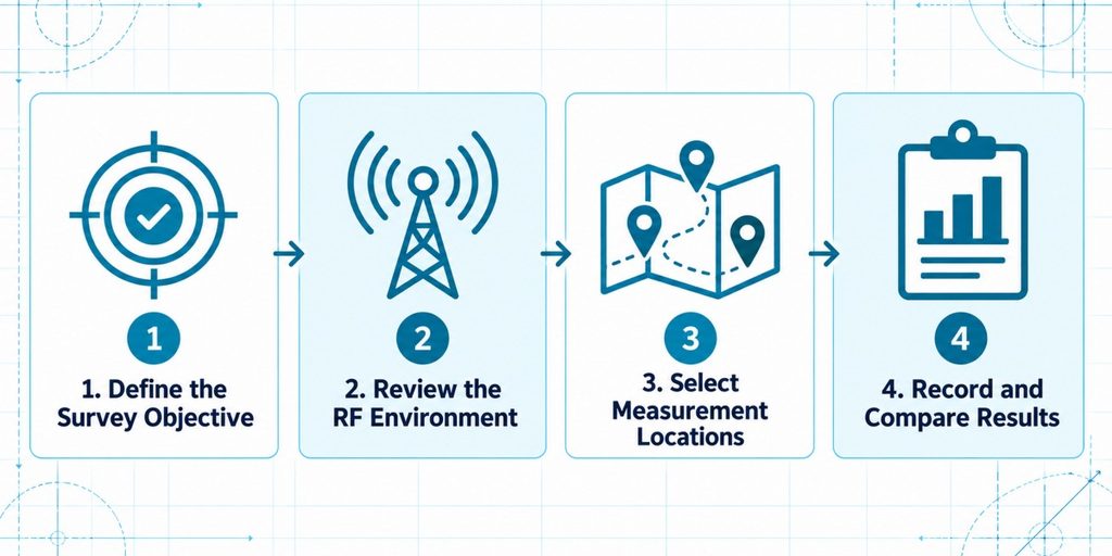
1. Define the Survey Objective
The objective determines the relevant field quantity, frequency range, and assessment criteria. Unlike RF readings, magnetic field measurements near power equipment require low-frequency instruments. When the power equipment or electrical layout is still being designed, magnetic field analysis can predict low-frequency conditions that an RF meter cannot measure.
2. Review the RF Environment
Engineers review likely sources, including Wi-Fi access points, rooftop antennas, cellular systems, two-way radios, and industrial wireless equipment. They note operating schedules and conditions that may affect the readings, such as intermittent transmission, occupied spaces, open doors, and nearby moving equipment.
3. Select Measurement Locations
Consistent probe handling, measurement height, and distances help comparisons, although the required sampling pattern depends on the governing method.
4. Record and Compare Results
Spot readings, spatial sweeps, mapped points, and time-based logging can each be appropriate. Results are then evaluated against the project’s defined criteria rather than an arbitrary universal threshold.
What Can Affect RF Survey Meter Readings?
- Source distance and antenna direction: Field distribution depends on transmitter power, antenna characteristics, position, and the measurement location.
- Reflections and shielding: Metal surfaces, building materials, glazing, and equipment can redirect or reduce signals, producing local peaks and low points.
- People and nearby objects: The surveyor or objects close to the probe can disturb the field, particularly in challenging measurement positions.
- Intermittent transmissions: Traffic, pulsed signals, and duty-cycled transmitters mean that a short reading may miss important operating conditions.
- Instrument behaviour: Frequency response, sensitivity, averaging mode, measurement duration, saturation limits, and calibration influence the reliability of results.
- Multiple simultaneous sources: A broadband measurement may combine contributions from several transmissions that need different exposure-limit weighting.
Where Are RF Survey Meters Used?
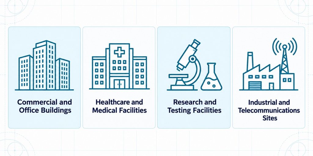
Commercial and Office Buildings
In offices, meters help document fields around Wi-Fi systems, antennas, and occupied spaces.
Healthcare and Medical Facilities
Hospitals contain wireless communication systems alongside sensitive diagnostic equipment. In MRI facilities, unwanted RF energy can affect imaging, while low-frequency magnetic disturbances create a separate engineering concern. RF shielding for MRI imaging rooms must therefore be considered alongside scanner-specific siting and performance requirements, not inferred from a general broadband reading alone.
Research and Testing Facilities
Laboratories may establish ambient RF levels before installing sensitive instrumentation or investigate signals affecting experiments. Where isolation is required, understanding what RF shielded enclosures are helps clarify why doors, seams, cable entries, and ventilation details influence shielding performance. RF shielded enclosures for medical and research facilities are specified around actual frequencies and equipment requirements.
Industrial and Telecommunications Sites
For base-station exposure evaluations, IEC 62232:2025 provides methods for determining RF field strength, power density, and related exposure quantities in its defined scope.
How RF Survey Meter Data Is Interpreted
For human RF exposure in Canada, Health Canada’s Safety Code 6 provides limits across 3 kHz to 300 GHz. Its technical guide describes measurement considerations, exposure categories, and averaging requirements. For projects in jurisdictions that adopt them, the ICNIRP 2020 RF guidelines cover 100 kHz to 300 GHz.
Exposure limits are not the same as equipment-immunity limits. A measured environment may meet human exposure criteria while still causing problems for a sensitive receiver or instrument. In those cases, equipment specifications, signal characteristics, and observed behaviour are more relevant than an exposure percentage.
Where several electromagnetic concerns coexist, EMF management plans can bring measurement findings, equipment criteria, and follow-up actions into the same project record. EMF testing also uses different measurement methods to assess RF fields and low-frequency electromagnetic fields.
When an RF Survey Meter Is Not Enough
A broadband meter can show that a field is present or elevated without proving what caused it or whether it is disrupting equipment. Electromagnetic interference (EMI) describes an unwanted effect on a device or system; field measurement alone does not establish that effect.
In EMI vs. EMC assessments, further investigation may involve frequency-selective measurements, time-based recording, controlled equipment tests, antenna measurements, or comparisons across operating schedules. Engineers must identify the source, frequency, coupling path, and affected equipment before choosing mitigation.
If the evidence indicates that radiated RF needs to be reduced within a defined space, RF shielded enclosures may be an option. Understanding how RF shielded enclosures prevent interference in sensitive systems also requires assessing penetrations and conducted paths. Shielding should not be specified from a single unexplained reading.
Use RF Measurements to Support Better Engineering Decisions
An RF survey meter provides a useful picture of combined radio-frequency field levels at selected locations. Its value comes from choosing the right instrument, measuring under representative conditions, and interpreting results against the correct exposure or equipment requirements.
C-INTECH provides engineering-led RF field surveys that can combine broadband measurements, spectrum analysis, documentation, and recommendations based on the facility’s technical needs. For a new installation, an interference concern, or an exposure assessment, contact C-INTECH to discuss the appropriate survey scope.
Frequently Asked Questions
1. Can an RF survey meter identify which device is causing a high reading?
Usually not if it is a broadband meter. It measures the combined field within its frequency range. A spectrum analyzer and targeted testing may be needed to associate the reading with a particular transmitter or device.
2. Why can an RF reading change when the meter moves only a short distance?
Signals arriving along different paths can reinforce or partially cancel one another. Reflections, antenna patterns, and obstacles may create noticeable differences between nearby measurement points.
3. Can metal walls or equipment make RF readings higher in some areas?
Yes. Metal can reflect RF energy and alter the local field distribution. This may produce higher readings at particular locations even while reducing transmission into other areas.
4. Are smartphone RF apps a substitute for a calibrated survey meter?
No. Most phone apps show cellular or Wi-Fi connection information rather than calibrated broadband electric-field measurements. Their readings are not a substitute for a suitably specified, calibrated instrument in a professional exposure survey.
5. How often should an RF survey meter be calibrated?
Follow the manufacturer’s recommended interval, the instrument’s calibration documentation, and the project’s quality requirements. There is no single interval suitable for every instrument and application. Instruments should also be checked when their performance is in doubt or after damage or significant changes.
