
An MRI scanner produces unexplained lines across an image. A scan that previously worked without problems now shows increased background noise. In another facility, image quality changes when nearby electrical equipment operates.
These symptoms may have different causes, but one possibility is electromagnetic interference (EMI).
Magnetic resonance imaging (MRI) systems depend on a highly controlled electromagnetic environment. Disturbances that have little effect on ordinary building equipment can become significant when they interfere with the weak signals an MRI scanner must detect.
EMI can originate from building electrical infrastructure, radio frequency (RF) sources, moving metallic objects, or changes in the surrounding environment. Depending on the interference mechanism, it may contribute to image artifacts, distortion, signal noise, or inconsistent system performance.
Understanding how these disturbances affect MRI performance helps architects, electrical engineers, healthcare planners, and facility teams identify potential problems before they affect equipment installation, commissioning, or clinical operations.
Why are MRI Systems Sensitive to Electromagnetic Interference?
MRI systems use magnetic fields and radio frequency signals to produce detailed images of structures inside the body.
Their operation relies on three main electromagnetic components:
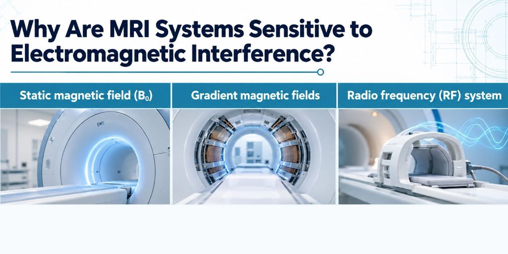
- Static magnetic field (B0): The main magnetic field establishes the magnetic environment required for imaging.
- Gradient magnetic fields: Controlled, time-varying fields encode spatial information, allowing the system to determine where signals originate.
- Radio frequency (RF) system: RF pulses excite the nuclear spins, while receiving coils detect the resulting electromagnetic signals used to reconstruct images.
These components must operate under carefully controlled conditions.
MRI receiving coils detect extremely weak signals. Unwanted RF energy can enter the receiving system and add noise or artifacts to the acquired data. Changes in the local magnetic field can also affect how spatial information is encoded.
The resulting interference depends on its frequency, magnitude, timing, and coupling path.
For example, RF interference entering through an opening in the scanner room’s shielding behaves differently from a fluctuating magnetic field generated by a nearby high-current electrical feeder.
The first may directly contaminate the received RF signal. The second may introduce changes in the magnetic field experienced by the scanner, potentially affecting image stability or geometry.
Both can affect imaging performance, but they require different engineering assessments and mitigation strategies.
This distinction is particularly important in healthcare and medical facilities, where MRI rooms must be coordinated with surrounding electrical, structural, mechanical, and architectural systems.
Common Sources of EMI Around MRI Suites
Not every electrical device near an MRI room creates an interference problem.
The actual risk depends on how the source operates, its distance from the scanner, the frequency and strength of the disturbance, and the MRI manufacturer’s siting requirements.
Several categories of sources deserve particular attention during facility design and troubleshooting.
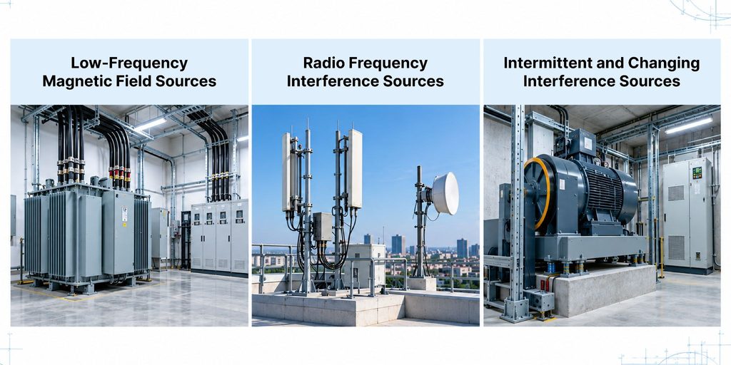
Low-Frequency Magnetic Field Sources
Building electrical distribution systems can generate low-frequency magnetic fields that extend beyond electrical rooms and equipment enclosures.
Potential sources include:
- Transformers and switchgear
- Electrical feeders and bus ducts
- High-current cable routes
- Electrical panels and distribution equipment
- Motors and variable-frequency drives
- Nearby utility and transportation infrastructure
Current magnitude, conductor configuration, separation distance, and operating circumstances all affect the magnetic field at the MRI site.
For example, a high-current feeder routed near an MRI suite may produce a different field distribution depending on how its phase and return conductors are arranged.
Similarly, equipment with variable electrical loads may produce changing field conditions rather than a constant background field.
These interactions can be evaluated through magnetic field analysis for buildings, allowing project teams to estimate potential exposure before electrical infrastructure is installed.
Radio Frequency Interference Sources
MRI receivers are designed to detect signals within specific RF frequency ranges. Unwanted energy reaching the receiver can interfere with signal acquisition.
Potential RF interference sources include wireless transmitters, communications infrastructure, electronic equipment, switching devices, and electrical systems that generate broadband RF noise.
However, external RF sources do not necessarily affect the scanner simply because they are nearby.
MRI rooms normally use dedicated RF shielding to attenuate unwanted signals.
Interference becomes more likely when RF energy enters through a weakness in the enclosure or originates from equipment operating inside the protected space.
Possible leakage paths include:
- Improperly closed or damaged RF doors
- Discontinuous shielding seams or joints
- Damaged viewing-window shielding
- Inadequately treated cable or service penetrations
- Faulty RF filters
- Openings or modifications that compromise shielding continuity
Research published in the Journal of Clinical Imaging Science describes how RF interference can produce characteristic image artifacts and how damage to MRI room shielding, including door contacts, can allow unwanted signals to enter the scan environment.
Intermittent and Changing Interference Sources
Some MRI interference problems are difficult to diagnose because they occur only under particular operating conditions.
For example, elevators, nearby vehicles, moving ferromagnetic equipment, and construction activity may change the magnetic environment around an MRI system.
A large metallic object moving through the scanner’s surrounding magnetic field can disturb local field conditions even when the object itself is not an electrical source.
An elevator travelling beside an MRI suite may therefore create a different type of disturbance from a transformer supplying the same building.
Interference may also vary with equipment operating schedules, electrical loading, or activity in adjacent spaces.
A single field measurement taken while the source is inactive may miss the conditions responsible for the problem.
This is why intermittent interference investigations should consider representative equipment operation and changes over time.
How EMI Affects MRI Performance
EMI does not always produce an immediately recognizable image defect.
Sometimes its first indication is reduced system consistency, unexplained measurement variation, or difficulty meeting equipment acceptance criteria. Let’s explore how EMI affects MRI performance.
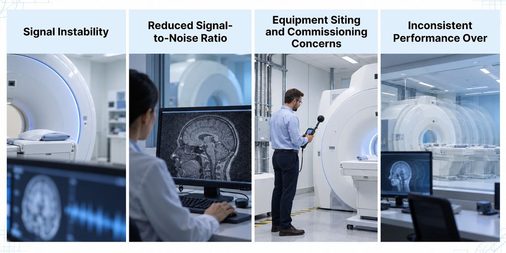
Signal Instability
MRI performance depends on maintaining sufficiently stable magnetic and RF conditions throughout signal acquisition.
When unwanted electromagnetic disturbances change during a scan, they can affect the consistency of the acquired information.
Depending on the source and imaging sequence, this may contribute to variations between repeated acquisitions or unexpected changes in reconstructed images.
Disturbances that remain stable may have different effects from those that fluctuate rapidly or occur intermittently.
Reduced Signal-to-Noise Ratio
Signal-to-noise ratio (SNR) describes the relationship between useful MRI signal and background noise.
When unwanted broadband RF energy enters the receiving system, it may increase the noise level without increasing the useful image signal.
The result is a reduction in SNR.
Lower SNR can make subtle image information harder to distinguish and reduce overall image clarity.
The impact depends on the strength and spectral characteristics of the interfering signal, the receiving system, and the imaging sequence.
Equipment Siting and Commissioning Concerns
MRI manufacturers specify environmental requirements for equipment installation and operation. These may include limits on external magnetic field disturbances, nearby moving metal, RF interference, and other site conditions.
When measured or predicted conditions exceed the applicable criteria, the project team may need to investigate the source or introduce mitigation before installation or acceptance.
Importantly, there is no single electromagnetic field limit that applies to every MRI scanner.
The correct assessment must use the requirements established for the particular system and project.
Inconsistent Performance Over Time
An MRI suite may perform acceptably during initial testing but experience problems after changes elsewhere in the building.
A newly installed electrical feeder, relocated mechanical equipment, modified RF penetration, or increased electrical load can change the electromagnetic environment.
These changes may explain why interference appears after a scanner has already entered operation.
It is therefore important to consider both the original installation conditions and subsequent changes to nearby infrastructure.
How EMI Affects MRI Image Quality
The most visible consequence of MRI interference is often an unexpected change in image quality.
The appearance varies depending on whether the disturbance originates from RF noise, external magnetic fields, scanner hardware, or another source. Let’s go over how EMI affects MRI image quality.
Noise and Loss of Image Clarity
Unwanted RF energy can add noise to the MRI signal, reducing the distinction between useful image information and background fluctuations.
Broadband interference may appear as a general increase in image noise rather than a clearly defined line or pattern.
When the noise becomes significant, anatomical detail may be less distinct, and the acquired images may not meet the facility’s expected quality requirements.
The severity also depends on the imaging sequence and how the receiving system responds to the interference.
Image Artifacts and Distortion
An MRI artifact is an image feature that does not accurately represent the anatomy being examined.
Electromagnetic interference can contribute to several types of image abnormalities.
A well-documented example is the zipper artifact, which can appear as one or more bright lines or bands across an MRI image.
Unwanted RF waves may infiltrate the receiving system and cause these abnormalities. A damaged RF door contact, for example, may allow external RF energy to reach the scanner and produce visible interference.
Research has also documented how broadband RF interference can increase image noise, while interference concentrated at particular frequencies can produce more localized lines or bands.
External magnetic field disturbances can affect image acquisition through a different mechanism. Changes in the magnetic field may introduce phase errors, instability, or spatial distortion, depending on their characteristics and the MRI sequence.
However, not every MRI artifact is caused by EMI.
Patient motion, physiological movement, scanner hardware, acquisition settings, and other factors can produce similar symptoms.
A reliable investigation therefore examines the actual source before attributing an image problem to the surrounding electromagnetic environment.
Effects on Imaging Workflow
Facility teams may need to redo procedures, look at equipment performance, or arrange for more testing when image quality starts to fluctuate.
If interference appears during commissioning, identifying the source can become necessary before the scanner is accepted for clinical operation.
For operational facilities, recurring problems may interrupt imaging schedules or require troubleshooting involving MRI service personnel, facility engineers, and shielding specialists.
Addressing the underlying environmental problem is generally more effective than repeatedly adjusting scanning procedures without establishing its cause.
How Are MRI EMI Problems Assessed?
An MRI EMI assessment confirms whether mitigation is necessary, identifies potential sources, and assesses whether the surrounding electromagnetic environment poses a credible interference risk.
The investigation should begin with the MRI system’s technical requirements rather than an assumed universal field limit.
Site Measurements and Source Identification
For an existing MRI suite, engineers may conduct on-site electromagnetic field and RF measurements.
The measurements help establish existing conditions and identify disturbances associated with nearby electrical infrastructure, equipment, or RF leakage.
Depending on the suspected mechanism, an assessment may examine field magnitude, frequency content, spatial distribution, and changes over time.
When interference is intermittent, measurements should reflect representative operating conditions.
For example, if image disturbances coincide with elevator operation, an investigation may need to evaluate field changes while the elevator moves rather than only measuring conditions while it is stationary.
Likewise, suspected RF leakage may require investigation of the room enclosure, including its doors, joints, windows, and penetrations.
C-INTECH’s MRI EMF Interference studies combine site measurements and engineering analysis to help project teams identify electromagnetic conditions that may affect MRI installations.
Finite Element Analysis and Magnetic Field Modelling
For new MRI facilities, some potential interference sources may not yet exist.
Electrical distribution equipment may still be in design, feeders may not be installed, and the MRI suite itself may not have been constructed.
Finite element analysis (FEA) allows engineers to estimate magnetic field conditions using a model of the proposed physical and electrical arrangement.
It can be used to assess sources such as transformers, switchgear, high-current conductors, and nearby magnetic materials.
Modelling may also help evaluate alternative equipment locations, conductor configurations, or magnetic shielding arrangements.
This approach allows project teams to compare potential design solutions before installation.
Our article on magnetic field analysis explains how measurements and numerical modelling support engineering decisions in sensitive environments.
FEA is particularly useful for magnetic field analysis, but it is not a substitute for every type of interference investigation. RF leakage and conducted electrical noise may require different measurement or analytical methods.
Manufacturer Siting Requirements
An important part of MRI interference assessment is determining what constitutes an acceptable electromagnetic environment.
The limits depend on the MRI manufacturer, scanner model, installation configuration, and type of disturbance.
Project-specific siting criteria may address:
- External alternating magnetic fields
- Static magnetic field disturbances and nearby ferromagnetic materials
- Moving metallic objects
- RF interference and enclosure shielding performance
- Interactions with adjacent equipment or MRI systems
These criteria provide the basis for comparing measured or predicted conditions against the requirements of the proposed installation.
An electromagnetic field level that is acceptable for one scanner should not automatically be assumed acceptable for another.
Ways to Reduce EMI Risk in MRI Environments
Effective mitigation begins with the identified source and interference mechanism.
There is no single shielding system that addresses every type of electromagnetic disturbance affecting an MRI installation.
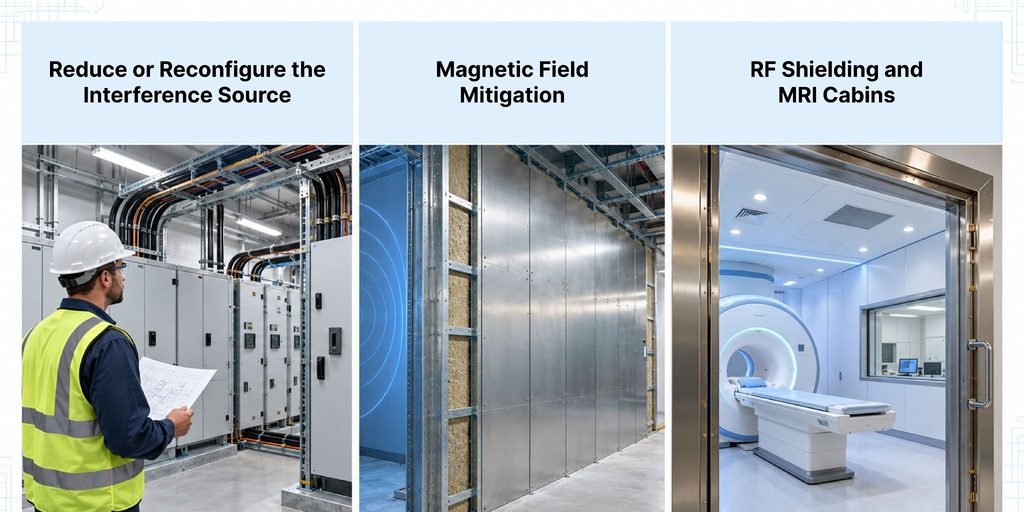
Reduce or Reconfigure the Interference Source
When possible, changing the source or its location can be an effective way to reduce interference.
For example, a design team may be able to move a transformer farther from the MRI suite, change a feeder route, or arrange conductors to reduce the magnetic field at the scanner location.
Increasing separation can also help where the source is a moving metallic object or nearby electrical equipment.
These measures are generally easier to consider before architectural layouts and major electrical infrastructure are finalized.
Once construction is complete, changes may involve additional structural, electrical, or operational constraints.
Magnetic Field Mitigation
When the source cannot be relocated or sufficiently reconfigured, magnetic field mitigation may be considered.
Depending on the source characteristics, options may include passive magnetic shielding or active field mitigation.
Passive shielding uses materials and configurations selected to modify the distribution of magnetic fields.
For low-frequency interference, the effectiveness of the shielding depends on material properties, thickness, geometry, field direction, and frequency.
As explained in our guide to magnetic shielding for sensitive facilities, shielding performance must be evaluated against the actual conditions rather than assumed from the material alone.
Active field mitigation systems take a different approach.
They use sensors, control electronics, and compensation coils to generate magnetic fields that oppose selected time-varying disturbances within a defined area.
These systems may be suitable for certain low-frequency interference problems, subject to the required field reduction, response characteristics, and installation conditions.
Neither passive nor active mitigation should be selected without a suitable engineering assessment.
RF Shielding and MRI Cabins
MRI rooms generally rely on an RF-shielded enclosure to reduce unwanted radio frequency energy entering the scanning environment.
These enclosures, often called MRI cabins, use conductive materials to form a controlled RF boundary around the scanner.
However, the shielding system must be continuous.
An enclosure with effective wall panels can still experience RF leakage through an improperly sealed door, damaged joint, untreated service penetration, or defective filter.
That is why RF shielding design must account for walls, floors, ceilings, windows, doors, ventilation systems, power connections, and communications interfaces.
For MRI rooms, C-INTECH provides custom RF enclosure design, installation, and verification services coordinated with the scanner and facility requirements.
Our guide, What Are RF Shielded Enclosures, explains how conductive materials, seams, filters, and penetrations work together to maintain shielding effectiveness.
RF shielding performance should be verified after installation and reassessed when renovations or modifications could compromise the enclosure.
It is also important to distinguish RF shielding from low-frequency magnetic field mitigation.
A conventional conductive RF enclosure does not automatically provide sufficient protection against magnetic fields from nearby 50/60 Hz electrical systems.
When Should EMI Be Evaluated in an MRI Project?
EMI assessment is most useful when its findings can still influence design decisions.
However, evaluation may also be needed during equipment installation, commissioning, or ongoing facility operation.
During Early Planning and Design
Before the MRI room location is finalized, the project team should review nearby electrical distribution systems, transformers, major feeders, elevators, adjacent imaging equipment, and external magnetic field sources.
This is an opportunity to identify potential conflicts while the building layout remains flexible.
Before MRI Equipment Installation
Once the installation location and building systems are defined, engineers can assess whether the expected electromagnetic conditions satisfy the manufacturer’s siting requirements.
Any necessary magnetic shielding, RF enclosure provisions, or electrical design changes should be coordinated before installation.
During Commissioning and Acceptance
After construction, field measurements and shielding verification can establish whether the completed environment satisfies the relevant project requirements.
This is particularly important where the installation includes specialized RF shielding or magnetic field mitigation.
Following Renovations or Facility Changes
The electromagnetic environment may change after an MRI system has entered service.
New electrical equipment, revised feeder routes, modifications to the RF enclosure, or changes in adjacent building use can introduce conditions that were not present during the original assessment.
For facilities managing these changes, EMF management plans for safe buildings provide a framework for identifying electromagnetic risks, documenting controls, and reassessing conditions when building systems change.
Common Mistakes in MRI EMI Planning
Several avoidable assumptions can complicate MRI installation or interference investigations.
- Assuming the RF enclosure solves every electromagnetic problem. RF shielding and low-frequency magnetic field mitigation address different mechanisms.
- Overlooking electrical systems outside the MRI room. Transformers, feeders, elevators, and equipment in adjacent spaces can influence field conditions at the scanner.
- Selecting shielding before identifying the source. A solution designed for the wrong frequency or interference pathway may not resolve the problem.
- Relying on one measurement. Intermittent sources may be missed when equipment is operating at low load or is inactive.
- Using generic field limits instead of manufacturer criteria. Acceptable conditions depend on the specific MRI system.
- Ignoring changes after commissioning. Renovations, new equipment, or damaged RF shielding may alter conditions that were previously acceptable.
A systematic approach to source identification, measurement, modelling, and verification helps project teams avoid these mistakes.
Protecting MRI Performance Starts With the Electromagnetic Environment
MRI image quality depends on more than the scanner itself.
Electrical infrastructure, nearby equipment, moving metallic objects, and RF shielding conditions can all influence the electromagnetic environment in which the system operates.
When interference occurs, the correct response is to determine its source, frequency, coupling path, and relationship to the scanner’s operating requirements.
That information allows engineers to distinguish between problems requiring electrical design changes, magnetic field mitigation, RF shielding repairs, or other corrective measures.
C-INTECH supports MRI projects through electromagnetic field measurements, FEA-based magnetic field analysis, MRI RF shielding, and interference mitigation.
If you are planning a new MRI installation, upgrading an existing suite, or investigating unexplained interference, contact C-INTECH to discuss the project conditions and appropriate engineering assessment.
Frequently Asked Questions
1. Can electromagnetic interference cause artifacts in MRI images?
Yes. RF interference can introduce unwanted signals into the receiving system and create image artifacts, including characteristic lines or bands. Magnetic field disturbances may also contribute to image instability or distortion. However, not every artifact is caused by EMI, so the source should be confirmed through appropriate investigation.
2. What are the most common EMI sources near an MRI suite?
Potential sources include transformers, switchgear, high-current feeders, electrical panels, motors, variable-frequency drives, RF-emitting equipment, damaged RF shielding, elevators, and moving ferromagnetic objects. The most significant source depends on the facility layout, operating conditions, and MRI system.
3. How do engineers test for MRI interference?
Engineers may use on-site magnetic field and RF measurements, interference source identification, shielding effectiveness testing, and engineering modelling. For proposed installations, FEA can predict magnetic field conditions before construction. Results are evaluated against the MRI manufacturer’s siting requirements and applicable project criteria.
4. Does every MRI room need RF shielding?
Clinical MRI installations typically require an RF-shielded room to reduce external radio frequency interference. However, shielding materials, enclosure design, and required attenuation depend on the MRI system and manufacturer specifications. There is no single RF shielding design appropriate for every installation.
5. Can nearby electrical equipment affect MRI image quality?
Yes, under certain conditions. Transformers, feeders, switchgear, and other equipment can produce magnetic fields that reach nearby MRI suites. Whether those fields cause interference depends on their strength, frequency, variation, distance, and the scanner’s susceptibility.
6. What is the difference between RF shielding and magnetic shielding for MRI?
RF shielding reduces unwanted radio frequency energy entering or leaving the MRI room. Magnetic shielding addresses static or low-frequency magnetic field conditions, depending on its design. The two systems serve different purposes, and some MRI installations require both.
7. When should an MRI interference study be completed?
Ideally, during early planning or design development, before the MRI location and surrounding electrical infrastructure are finalized. Verification may also be required before commissioning. Existing facilities should consider reassessment when renovations, electrical upgrades, or equipment changes could alter the electromagnetic environment.
