
Electromagnetic interference (EMI) is an unwanted electromagnetic disturbance that can disrupt or degrade the performance of electrical and electronic equipment. Electromagnetic compatibility (EMC) is the ability of equipment and systems to operate properly in their intended electromagnetic environment without causing or experiencing unacceptable interference.
Put simply, EMI is the problem, while EMC is the performance objective.
The EMI vs. EMC distinction matters in buildings where sensitive equipment operates alongside electrical distribution systems, wireless communications, motors, or other electromagnetic sources. Hospitals, research laboratories, data centres, and industrial facilities may all need to consider EMI and EMC during design, equipment installation, or troubleshooting.
EMI vs. EMC: The Core Difference
Although EMI and EMC are closely related, they describe different aspects of electromagnetic performance.
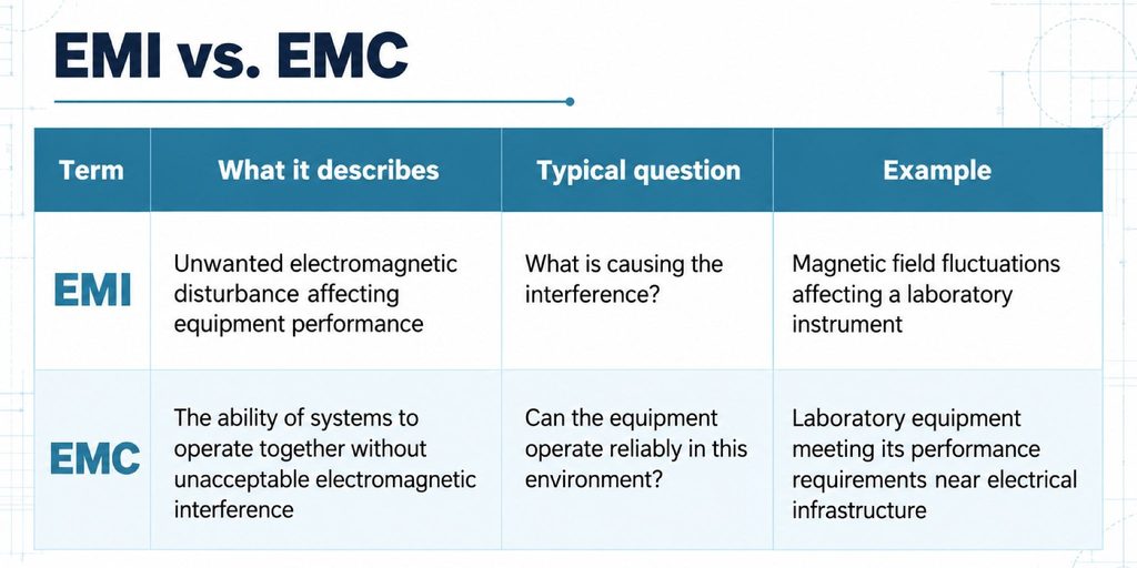
What Is EMI?
Electromagnetic interference occurs when unwanted electromagnetic energy affects equipment, signals, measurements, communications, or control functions.
EMI can reach equipment through two main mechanisms:
- Conducted EMI: Disturbances travel through electrical connections, including power cables, signal wiring, and shared conductive paths.
- Radiated EMI: Electromagnetic energy couples through space into equipment or its connected wiring, through electric fields, magnetic fields, or propagating radio-frequency waves.
Common building-related sources include transformers, switchgear, bus ducts, high-current feeders, motors, variable-frequency drives, and wireless transmitters.
For example, an electrical feeder installed near a sensitive laboratory may produce a time-varying magnetic field. If that field exceeds the instrument’s tolerance, measurements may become unstable.
The presence of the field alone, however, does not establish that harmful EMI is occurring.
What Is EMC?
Electromagnetic compatibility describes whether equipment can function acceptably in its intended electromagnetic environment while avoiding unacceptable interference with other equipment.
EMC involves two related considerations:
- Emissions: Controlling electromagnetic disturbances generated by equipment so they do not exceed applicable limits or disrupt nearby systems.
- Immunity: Ensuring equipment can tolerate specified electromagnetic disturbances while maintaining the required level of performance.
Achieving EMC does not require eliminating electromagnetic fields. Electrical systems naturally produce them during normal operation.
The objective is to ensure that emissions, environmental conditions, and equipment susceptibility remain compatible with the intended application.
A device can therefore operate in an environment containing measurable electromagnetic fields and still meet its EMC performance requirements.
How EMI and EMC Relate
EMI and EMC are best understood through the relationship between an electromagnetic source, its coupling path, and the equipment being affected.
Consider a research facility with a high-current electrical distribution system near an electron microscope.
The electrical system generates magnetic fields. Those fields may couple into the microscope, potentially affecting image stability.
Engineers examine three elements:
- Source: The equipment or system generating the electromagnetic disturbance.
- Coupling path: How the disturbance reaches the affected equipment, including wiring, conductive connections, or electromagnetic fields.
- Receptor: The equipment whose performance may be affected.
EMI can prevent EMC from being achieved when the disturbance exceeds what the equipment can tolerate.
However, a field measurement alone does not prove that equipment is experiencing interference. The measured conditions must be evaluated against manufacturer limits, equipment sensitivity, relevant standards, or project-specific performance criteria.
For building projects, magnetic field analysis for safe and compliant building design explains how modelling and measurements can help identify potential interference risks.
Project-specific magnetic field analysis can also evaluate proposed electrical layouts before construction, when equipment locations and routing options remain flexible.
Common Sources of EMI in Buildings and Facilities
Electromagnetic disturbances can originate inside a building or from surrounding infrastructure. Their potential impact depends on frequency, magnitude, operating conditions, coupling paths, and equipment sensitivity.
Low-Frequency Electrical Sources
Transformers, switchgear, electrical rooms, bus ducts, high-current feeders, and large motors are common sources of low-frequency electromagnetic fields.
In Canadian buildings, power-frequency magnetic fields are typically associated with 60 Hz electrical systems, although harmonics and switching equipment may introduce additional frequencies.
Conventional walls, floors, and ceilings can all be penetrated by low-frequency magnetic fields. Standard building materials do not necessarily provide meaningful attenuation at these frequencies.
Sensitive equipment located near electrical distribution infrastructure may therefore require additional evaluation.
Radio Frequency and Wireless Sources
Cellular systems, Wi-Fi networks, radios, antennas, and other wireless transmitters generate RF energy.
RF interference differs from low-frequency magnetic interference in its frequency range and coupling behaviour.
For example, unwanted RF energy may enter equipment through poorly shielded cables, openings in enclosures, or susceptible electronic circuits.
The appropriate assessment and shielding methods depend on the operating frequencies, signal characteristics, and affected equipment.
Transit and Industrial Sources
Electrified transit systems, industrial machinery, welding equipment, and variable-frequency drives can produce electromagnetic disturbances under particular operating conditions.
For developments near Toronto Transit Commission (TTC) infrastructure, changing traction currents may create magnetic field conditions that require evaluation when sensitive equipment or systems are planned nearby.
Industrial facilities may also experience conducted electrical noise or high-frequency disturbances associated with switching equipment.
These conditions do not automatically indicate an EMI problem, but they may justify investigation when equipment performance requirements are stringent.
Why EMC Matters for Sensitive Equipment and Facilities
Poor electromagnetic compatibility can lead to operational problems that are difficult to identify without targeted measurements and analysis.
Depending on the equipment and interference mechanism, potential consequences include image artifacts, unstable measurements, communication errors, control-system disturbances, equipment malfunction, or failure to meet manufacturer siting criteria.
Certain facilities require particular attention:
- Healthcare and MRI facilities: Imaging equipment may have strict requirements for RF conditions, magnetic field stability, and nearby electrical infrastructure.
- Research laboratories: Electron microscopes, precision measurement instruments, and other scientific equipment may be sensitive to relatively small disturbances.
- Data centres and telecommunications facilities: Communications and electronic systems depend on reliable signal transmission and equipment operation.
- Industrial facilities: Automation equipment, sensors, and control systems may be affected by conducted or radiated disturbances.
- Government and secure facilities: Specialized equipment and RF-controlled environments may require defined electromagnetic performance and verification criteria.
EMC risk is not determined by field strength alone. Distance, frequency, source behaviour, shielding, coupling paths, equipment immunity, and required performance all influence whether interference becomes significant.
How Engineers Identify EMI and EMC Problems
EMI and EMC investigations should begin with the equipment’s operating requirements and the electromagnetic conditions that could affect them.
Site Measurements and Field Surveys
On-site measurements help engineers identify field strength, frequency content, spatial variation, and possible interference sources.
Measurements may be taken at multiple locations and during different operating conditions, particularly when disturbances are intermittent.
For RF-related investigations, RF field surveys use appropriate measurement instruments and spectrum analysis to characterize signals and identify potentially unwanted RF conditions.
A survey can establish the electromagnetic environment, but equipment performance testing or further analysis may be necessary to confirm the cause of a malfunction.
Modelling and Engineering Analysis
During design, electromagnetic modelling can estimate field conditions before electrical infrastructure is installed.
For low-frequency magnetic fields, finite element analysis (FEA) can help engineers evaluate source configurations, equipment separation, feeder routing, and proposed shielding.
Modelling is particularly useful when electrical rooms, sensitive laboratories, or imaging facilities are being planned on adjacent floors.
It allows the design team to compare alternatives before construction makes changes more difficult.
Compliance and Equipment Criteria
EMI and EMC testing help engineers evaluate electromagnetic emissions, equipment immunity, and potential interference risks against applicable performance requirements.
Depending on the facility and equipment, EMC evaluation may involve manufacturer siting requirements, project-specific limits, and recognized electromagnetic standards.
For example, the IEC TR 61000-1-1:2023 addresses fundamental EMC terminology and distinguishes standardized testing from measurements performed at actual installation sites.
Product EMC compliance and building-level EMI investigations are not identical. A device that meets laboratory test requirements may still encounter electromagnetic conditions outside those tests at its final installation location.
C-INTECH’s certifications and compliance services support projects requiring assessment against applicable electromagnetic engineering standards and defined performance criteria.
How EMI Is Reduced, and EMC Is Improved
Effective EMI mitigation begins by identifying the disturbance source and coupling mechanism. Installing shielding without this information may fail to address the actual problem.
Source Control and Equipment Layout
The first approach is often to reduce interference through practical design changes.
Increasing separation between electrical infrastructure and sensitive equipment, relocating equipment, revising cable or bus duct routes, or reducing emissions at the source may improve electromagnetic compatibility.
These options are especially valuable during design, when layouts can still be adjusted.
Magnetic and RF Shielding
Where layout changes are insufficient, shielding may be required. Where power-frequency magnetic fields are the concern, ELF field mitigation can integrate engineered shielding into the building around the source and protected space.
However, low-frequency magnetic shielding and RF shielding operate differently. The appropriate design depends on frequency, field strength, geometry, and required attenuation.
The broader principles of electromagnetic shielding in buildings explain why EMF, RF, and electromagnetic pulse protection require different engineering approaches.
For low-frequency applications, magnetic shielding for sensitive facilities may involve specialized high-permeability or conductive materials, selected according to the field characteristics and performance requirements.
For higher-frequency applications, RF shielded enclosures use conductive barriers and carefully treated openings to attenuate unwanted RF energy.
Shielding performance depends on the complete installation, including doors, ventilation openings, cable penetrations, and construction details.
Other EMI Mitigation Methods
Depending on the source and coupling path, additional measures may include filtering, grounding and bonding improvements, cable routing changes, equipment-level protection, or active magnetic field cancellation.
These measures are not interchangeable. A filter designed for conducted interference will not necessarily address a low-frequency magnetic field passing through a wall.
Mitigation should be selected against measurable performance objectives, followed by verification under representative operating conditions.
When to Bring in an Electromagnetic Engineering Specialist
An EMI or EMC assessment is most useful when a project involves sensitive equipment, significant electromagnetic sources, or performance requirements that cannot be confirmed through conventional building design alone.
Specialist involvement may be appropriate:
- During early design: When sensitive rooms are located near transformers, electrical distribution systems, or transit infrastructure.
- Before equipment installation: When manufacturer siting limits must be verified.
- During troubleshooting: When measurement drift, image artifacts, communication errors, or intermittent equipment problems suggest interference.
- During compliance review: When documented measurements, engineering analysis, shielding design, or verification testing are required.
C-INTECH’s EMF/RF shielding process covers the progression from consultation and field assessment through engineering analysis, mitigation design, installation, and verification.
Understanding the Difference Helps Prevent the Wrong Solution
EMI describes unwanted electromagnetic interference that affects equipment performance. EMC describes the ability of equipment and systems to function reliably together in their electromagnetic environment.
The distinction helps project teams decide whether they need to investigate an existing disturbance, evaluate future field conditions, verify equipment requirements, or develop a mitigation strategy.
For facilities with sensitive equipment, the most effective approach is to identify potential sources early, establish measurable performance criteria, and confirm that the selected controls address the actual interference mechanism.
If your project requires electromagnetic field assessment, shielding design, or interference mitigation, request a project assessment to discuss the relevant engineering requirements with C-INTECH.
Frequently Asked Questions
1. What is the main difference between EMI and EMC?
EMI is unwanted electromagnetic interference that degrades equipment performance. EMC is the ability of equipment to operate acceptably in its electromagnetic environment without causing unacceptable disturbances to other systems. EMI describes an interference problem; EMC describes the desired operating condition.
2. Can a device pass EMC requirements and still experience interference on site?
Yes. Standardized EMC testing evaluates equipment under defined test conditions. An actual installation may expose the equipment to different frequencies, field strengths, or disturbances. Passing product-level EMC requirements does not automatically guarantee compatibility with every installation environment.
3. What are the most common sources of EMI in buildings?
Common sources include transformers, switchgear, high-current feeders, bus ducts, motors, variable-frequency drives, wireless transmitters, and nearby transit or utility infrastructure. Whether these sources cause interference depends on their operating characteristics, coupling paths, and the sensitivity of nearby equipment.
4. Is EMI the same as EMF?
No. Electromagnetic fields (EMF) are physical fields produced by electrical currents, energized equipment, and electromagnetic radiation. EMI occurs when electromagnetic disturbances negatively affect equipment operation. An electromagnetic field can exist without causing interference.
5. How do engineers test for EMI or EMC problems?
Engineers may use electromagnetic field measurements, spectrum analysis, conducted emissions testing, immunity testing, equipment performance checks, and engineering modelling. The appropriate methods depend on whether the objective is diagnosing site interference, verifying equipment compatibility, or demonstrating compliance with applicable standards.
6. Can shielding solve every EMI problem?
No. Shielding can reduce particular types of electromagnetic interference, but it is not a universal solution. Some disturbances require source reduction, filtering, improved cable routing, grounding and bonding changes, or equipment relocation. The correct approach depends on the frequency and coupling mechanism involved.
